Pure Inductive Circuit Phasor Diagram
Inductive purely inductor What is rlc series circuit? Phasor diagram circuit derive connected source current voltage expression flowing inductor ideal using shaalaa fig physics ac lcr series
AC supply to pure inductor (theory, phasor & waveforms
Ac supply to pure inductor (theory, phasor & waveforms Ac inductor circuits Ac through pure inductor
Ac through pure resistor : phasor diagram & average power
Inductor & capacitor phasor diagram with respect to v&i ||electrical9.17. draw and explain phasor diagram for voltageand current in a Phasor diagram inductor capacitor circuitPhasor pure diagram resistor ac through power average.
Electrical engineering world: phasor diagram and impedance triangle forAc supply to pure inductor (theory, phasor & waveforms Inductive pure purely consumed phasorPhasor diagram ( inductive load) for a single phase transformer.

Phasor transformer inductive
Diagram transformer vector phasor load phase single inductiveDiagram circuit pure capacitive represents phasor resistive inductive question waveforms What is a pure inductive circuit?Phasor diagram resistive pure circuits.
What is a pure inductive circuit?Why is the inductive reactance or capacitive reactance phasor on the Phasor diagram for pure resistive circuitsSolved the diagram represents a: a.pure capacitive.
%2BCircuit.jpg)
Circuit phasor series rlc reactance inductive diagram voltage capacitive parallel analysis vector impedance reference source electrical axis imaginary why power
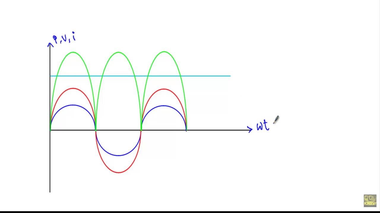
Inductor pure inductive phasor ac circuit voltage current waveforms supply lags circ phase angle shown text figure look so willInductive circuit pure power purely waveform ac inductor instantaneous supply phasor current voltage theory waveforms shown figure Triangle impedance phasor diagram inductive capacitive circuitCircuit inductive pure diagram phasor voltage alternating applied waveform.
Inductive waveform phasor purely compressor consumedPhasor circuit rlc series diagram voltage current ac power draw phase impedance triangle reactive angle phasors physics lagging length questions Using phasor diagram, derive the expression for the current flowing inPhasor inductive diagram ac impedance relation circuit showing figure.

Transformer on load condition
.
.


AC supply to pure inductor (theory, phasor & waveforms

Phasor Diagram for Pure Resistive Circuits | Electrical Engineering

What is RLC Series Circuit? - Phasor Diagram & Impedance Triangle

Inductor & Capacitor Phasor Diagram with Respect to V&I ||Electrical

PHASOR DIAGRAM ( INDUCTIVE LOAD) FOR A SINGLE PHASE TRANSFORMER - YouTube
AC through Pure Resistor : Phasor Diagram & Average Power - YouTube
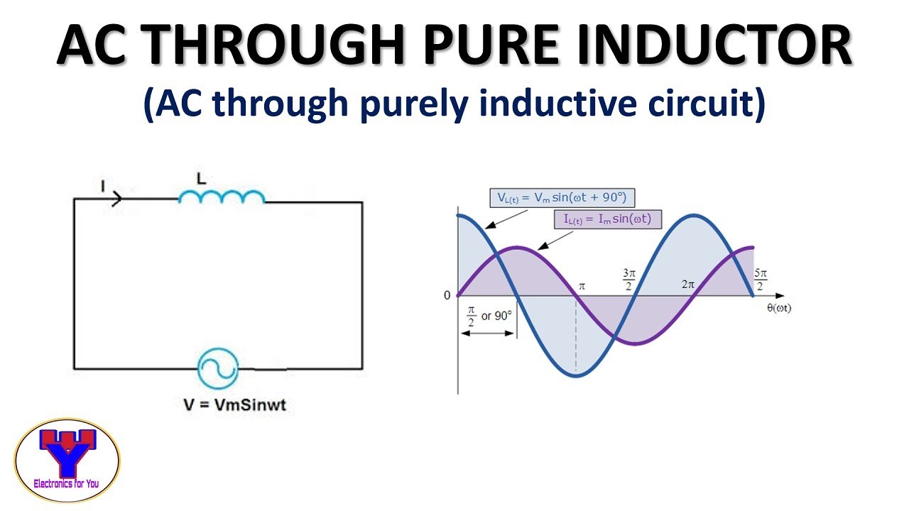
AC through pure Inductor | AC through purely inductive circuit - YouTube

Using Phasor Diagram, Derive the Expression for the Current Flowing in